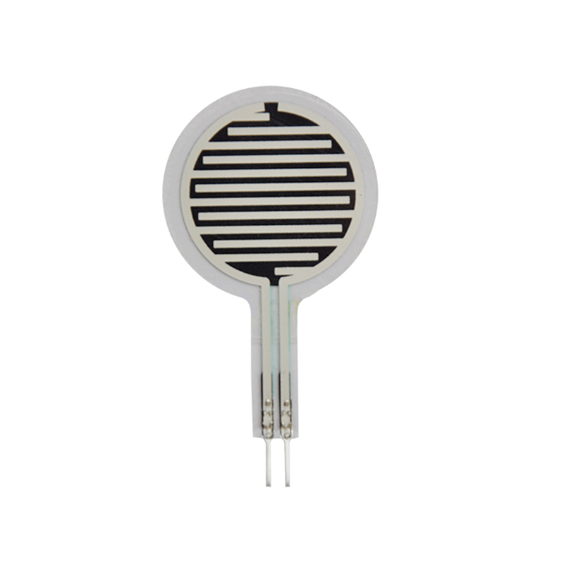
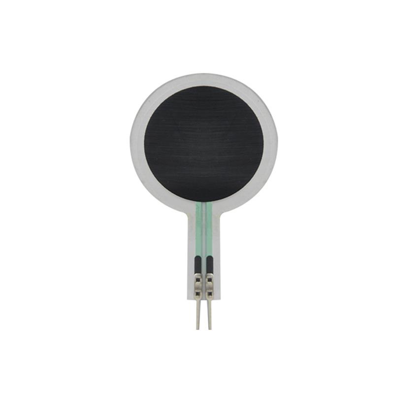
Wearable FSR Sensor: Flexible Gait Analysis Piezoresistive insole force sensitive resistor

  • Model:Insole FSR-12
  • Type:Multipoint / Matrix force sensor (optional)
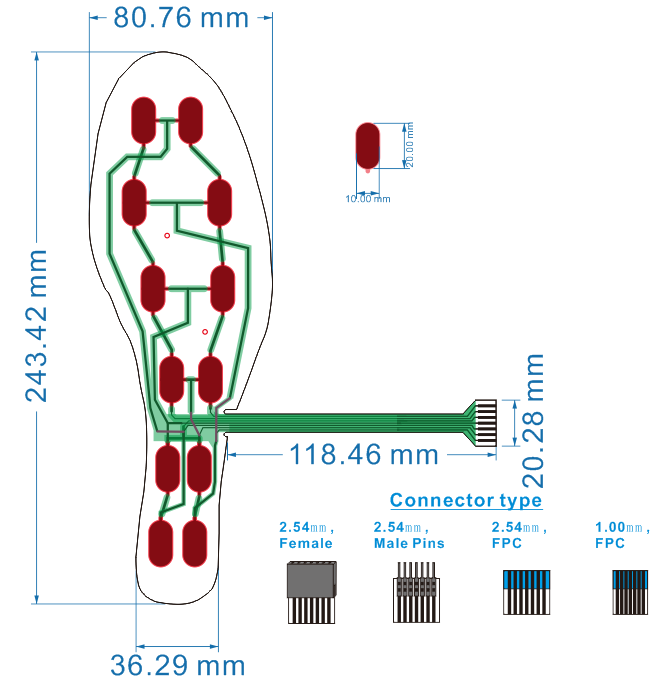
  • Sensor size(single point sensor):20.5*11mm
  • Sensor quantity:12
  • FSR Thickness:<0.3mm
  • gait analysis,gait analysis sensor,gait analysis equipment
  • gait analysis systems,portable gait analysis system,foot mapping sensor system
  • Insole sensor,insole pressure sensor,pressure sensor insole

Product Specification

Description :
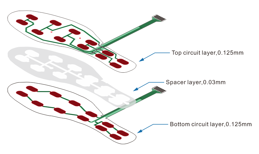
This type of product is used in the insole, to measure the pressure distribution and dynamic changes of on the insole. This product has a total of 12 sensing points, evenly distributed in the contact position between the foot and the insole, can collect the force applied positions and pressure changes information when user walking, running, jumping.
ModelType
Insole FSR-12Multipoint / Matrix force sensor (optional)

Features and Benefits :

  • Sensitive response – minimum trigger force at each sensor point is 50g.
  • Large force range – each insole can withstand more than 100KG of pressure.
  • Ultra thin -the sensor total thickness is about 0.3mm.
  • Convenient data acquisition – using matrix circuit design, easy to collect pressure distribution and change data.
  • Convenient installation and integration – our company can provide data acquisition and transmission module, you can easily complete the installation of the collector.
  • Low Cost – This sensor offers a low cost advantage over other forms of sensors, especially for multi-point distributed acquisition pressure applications.

ItemData
Sensor size(single point sensor)20.5*11mm
Sensor size(sinSensor quantity12
Force measure range(single point sensor)50G ~ 20KG
Force measure range(1 piece insole sensor)10KG~100KG
FSR Thickness<0.3mm
Force repeatable (part to part)±10%
Off resistance2MΩ
Force resolutionContinuous
Response time<1 ms
Operating temperature-20℃~60℃
Life time2 million
ConnectorFemale 2.54mm / Male pins 2.54 / FPC 2.54 or 1.0mm

Download

ntegration and usage methods:
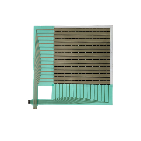
The Foot Pressure Sensor is a matrix pressure sensor that can be interpreted as a 3 row by 4 column matrix circuit design with a total of 12 sensor points . There are two circuits layer on the structure, the upper circuit layer connector has 3PINs, the lower circuit layer connector has 4PINs.
Usually when integrate the insole to PCB, the three PINs of the upper circuit can be connected to the channel switch chip, an RM is connected in series on each PIN, and connect to GND. The four pins of the lower circuit are connected to the ADC1~4 (as shown in the figure below). At the beginning of the operation, the switch channel chip will turn on the power channel CH1~CH3 in turn, and the MCU will collect the voltage on ADC1~ADC4 in turn, By compare and calculate the data from ADC, and obtain the distribution information of the pressure weight at all the sensor points.
Tips:The order of collecting voltage is as followed.CH1 is open(at same time CH2&3 are closed),MCU collect the voltage from ADC1 to ADC4,these voltages are form Sensor point 1~4#,then close CH1 and open CH2,MCU collect the voltage from ADC1 to ADC4,these voltages are form Sensor point 5~8#,then close CH2 and open CH3,MCU collect the voltage from ADC1 to ADC4,these voltages are form Sensor point 9~12#.
PhotoStructure
Size

Contact US

Are you ready? Contact our pre-sales engineers immediately to provide you with relevant samples or customized FSR sensor projects!

Translate »